
")
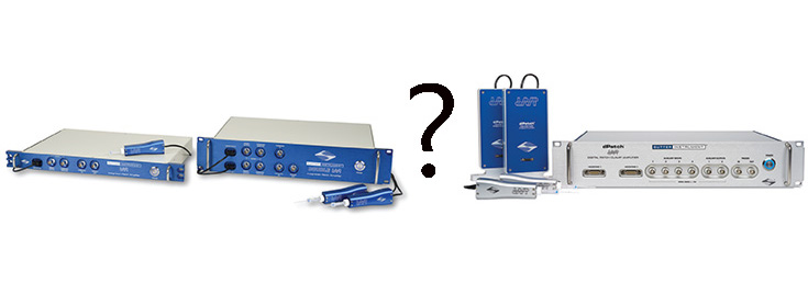
dPatch®

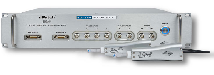

Available in either a single- or dual-headstage configuration, the dPatch amplifier’s architecture makes swapping headstages, or adding a second one to a single-headstage version, a plug-and-play operation. The two headstages are independently configurable for either voltage clamp or true high-speed current clamp. Data is streamed from each headstage in parallel and fully synchronized.
5 MHz sampling rate, up to 22-bit resolution
One unique feature with dPatch is the headstage data sampling system. Each headstage is continually sampled at 5 MHz. Output filtering has ten settings between 1 MHz and 1 kHz. A resolution of 18 bits is achieved at 1 MHz. For lower filter settings, automatic downsampling increases resolution while optimizing data rates. At a bandwidth setting of 1 kHz the dPatch system provides a signal resolution of better than 22 bits.
Built-in data acquisition system means no third-party digitizer
Using a multiplexer-free design, the dPatch provides 8 fully differential analog input channels, 4 analog output channels, and 16 digital outputs (TTL). All I/O channels are sampled continuously (200 kHz for analog inputs, 250 kHz for analog and digital outputs) and available through the user interface.
SutterPatch® Software
The dPatch amplifier, in combination with SutterPatch software, has been engineered to automatically capture and store all amplifier settings, stimulus information and external experiment parameters, and associate them in time with the raw data traces. This includes all amplifier and acquisition settings, as well as timing and progress of the experiment. Fully integrated computer control of the amplifier stages means that the acquisition software is aware of the internal state of the amplifier and digitizer at all times and can track any changes that may occur. This is independent of whether a change is triggered automatically or initiated by the user.
Tracking of Other External Data
In addition to status changes in connected hardware that are automatically tracked, the researcher can manually trigger tags to document events like stimulus application using instruments not connected to the amplifier.
Information about environmental parameters and a more detailed specification of sample properties can be recorded and stored with the raw data. A total of over 500 metadata attributes are supported. Examples include: animal species, strain, date/time when a cell sample was prepared, recording solutions, pipette resistance, hardware properties, and detailed information about stimuli applied.
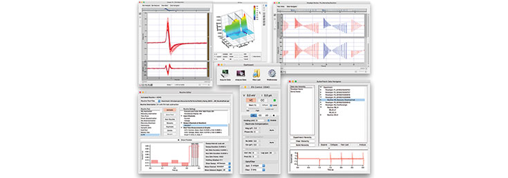
Data Visualization and Analysis
SutterPatch software has been designed to simplify the navigation and analysis of complex datasets. The scope window supports multiple view modes in both two-dimensional and an innovative three-dimensional display. The 3D view is particularly useful during assay development. Built on top of the latest version of the proven Igor Pro platform, SutterPatch combines native Igor Pro functionality with a wealth of features that are tailored to electrophysiology applications. Both the newcomer and the experienced user of patch clamp programs will feel comfortable using SutterPatch software.
Application modules provide focused functionality for particular applications.
Currently available:
- Event Detection Module: A deconvolution algorithm that excels at detecting miniature synaptic events even on a noisy background
- Action Potential Analysis Module: Phase plane plot, timing and waveform statistics.
- Camera Module: An easy way to document the identity and condition of the recorded cell
A Laboratory Workhorse
While dPatch is ready for cutting-edge research, its feature set makes it immediately valuable in any lab setting.
- Three headstage feedback ranges for optimal whole-cell and single-channel recording
- Automated compensation of electrode and whole-cell capacitance
- Series resistance compensation
- Simple cabling, quick and easy set-up
- High dynamic range of digitizer means no need for variable gain stages
- High speed of digitizer means no concern about sample rate
COMMON APPLICATIONS
- Single-channel recordings
- Auditory research and other rapidly changing signals
- Tissue slice recordings
- Cultured cell experiments
- Cell line studies from adherent or dispersed cells
- Optogenetics
FEATURES
- Fully integrated single- or dual-headstage patch clamp amplifier and data acquisition system ensures quick and easy setup
- Optimized for whole-cell patch clamp recordings in tissue slices, adherent or dissociated cells
- Full computer control provides automated compensation of electrode and whole cell capacitance
- Voltage and true current clamp capability for complete characterization of cells' electrical activity
- Line frequency reduction in SutterPatch
- High bandwidth enables characterization of the fastest signals
- Three Headstage feedback ranges for single-channel and whole-cell patch clamp recordings
- Comprehensive digital compensation circuitry provides utmost precision and signal fidelity
- Bundled SutterPatch software provides versatile data management, intuitive navigation and streamlined data analysis.Fully integrated patch clamp amplifier and data acquisition system ensures quick and easy setup
SPECIFICATIONS

The dPatch Integrated Digital Patch Clamp Amplifier is a computer-controlled single- or dual-headstage amplifier optimized for both single-channel and whole-cell recording applications.
Amplifier
- Hardware architecture enables all data conversion to be performed near the preparation, well away from known noise sources, such as power supplies and high-speed digital circuitry.
- Voltage clamp and true current clamp modes with smart switching between modes to avoid current artifacts
- Three choices of headstage feedback elements to optimize both single-channel and whole-cell recording Feedback
* Capacitive feedback range is optimized for single-channel voltage clamp recordings.Feedback
ElementRange Analog
BandwidthNoise
10 kHz BWPipette
Compensation
RangeSeries
Resistance
RangeCell
Capacitance
RangeCapacitive ±20 nA > 500 kHz < 0.2 pArms 10 pF N/A* N/A* 500 MΩ ±20 nA > 200 kHz < 1 pArms 10 pF 100 MΩ 100 pF 50 MΩ ±200 nA > 200 kHz < 2 pArms 10 pF 10 MΩ 1000 pF
Whole-cell compensation and current clamp mode are disabled with this range. - Automatic compensation routines for pipette compensation and whole-cell compensation
- Series resistance prediction and correction independently programmable
- 8-pole Bessel filter 1, 2, 5, 10, 20, 50, 100, 250, 500, 1000 kHz
- Signal processing of filter output to increase resolution and reduce data file size
- Resolution over 22 bits at 1 kHz filter setting
- High dynamic range of analog to digital converters alleviates need for variable output gain stages
- Holding potential ±1000 mV
- Current clamp bridge compensation and pipette capacitance compensation
- Slow holding potential tracking compensates for drift during current clamp recordings
Data Acquisition
- Embedded data acquisition system eliminates the need for an external data acquisition board
- 5 MHz sampling rate per headstage, 22-bit resolution
- Auxiliary input / output for control of other instrumentation:
- 8 Auxiliary analog inputs, 16-bit fully differential, ±10 V input, each continuously sampled at 200 kHz
- 4 Analog outputs, 16-Bits, ±10 V output each continuously updated at 250 kHz
- 16 Digital outputs (TTL) each running at 250 kHz
- Independent Trigger IN / Trigger OUT for synchronization of external instrumentation analog input channels (± 10 V)
- Single SuperSpeed USB 3.0 connection controls data acquisition and amplifier
- Complex command waveforms
- Data acquisition can be initiated by an onboard microsecond clock or external (TTL) trigger
SutterPatch® Software
- Built on the foundation of Igor Pro 7 (WaveMetrics, Inc.)
- Paradigms and Routines provide complete experimental control
- Waveform Editor for easy creation of even the most complex stimulus patterns or user-defined templates
- Associated metadata stores all relevant information regarding your experiment
- Comprehensive data analysis routines and publication quality graphics
- Requires Windows 7 (64-bit) or Mac OS X 10.11 (El Capitan), or newer versions
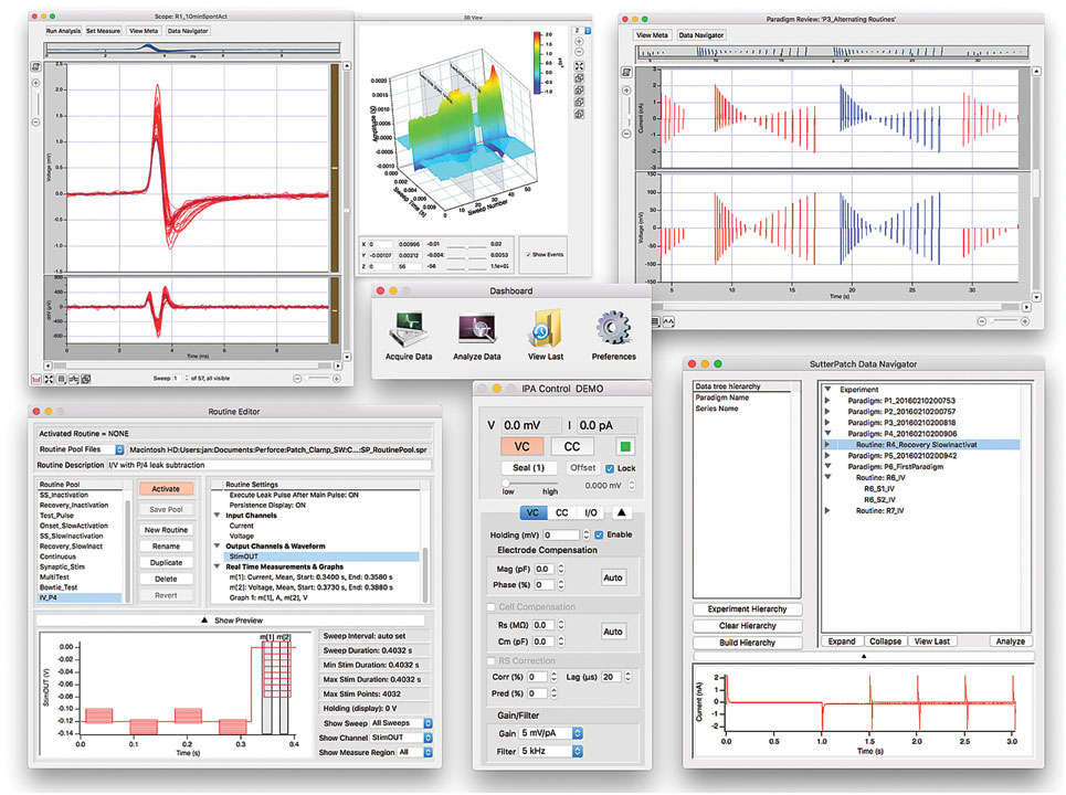
Screenshot of SutterPatch Software
TECHNICAL SPECIFICATIONS
Dimensions
dPatch®: 48.2 cm × 28 cm × 9 cm
dPatch® Preamplifier: 19.5 cm × 9 cm × 3 cm
dPatch® Headstage: 10 cm × 3.5 cm × 1.9 cm
Weight
dPatch®: 6.8 kg
Electrical
110/240 V
50/60 Hz power line
Accessories
![]()
EH-P170
Polycarbonate pipette holder
![]()
EH-Q170
Quartz pipette holder
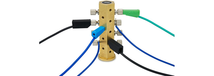
Ground point
for the electrophysiological setup
BOB
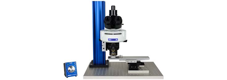
Well suited microscope
for the electrophysiological setup
Also See:
SutterPatch®"
Software
(Sutter Instrument)
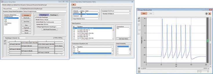
Dynamic Clamp
for the
dPATCH® Patch Clamp Amplifier
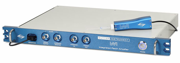
IPA® / DOUBLE IPA®
Integrated Patch Clamp
Amplifier System
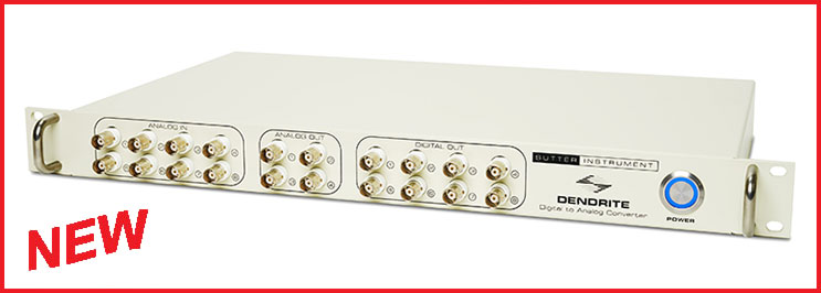
Dendrite ™
Data Acquisition,
Management and Analysis System
Comparison of IPA with dPatch
(PDF file)
![]()
IPA Publications
(PDF file, external link)