
")
-
Startseite

-
Produkte
-
Mikroinjektionssysteme
-
Iontophorese
- MVCS-Series
MVCS-Series

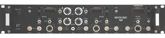
MVCS systems are designed for ejection of drugs or other ionic compounds through micropipettes by the application of current in the nA or µA range.
Very accurate current pumps guarantee precise application of drugs. Some models allow very fast drug applications down to the sub-millisecond range with currents from tens of pA up to hundreds of µA. Therefore, systems can be used to simulate synaptic events. The unique operating and display elements of these instruments facilitate the application of drugs in physiological, pharmacological, and biochemical studies.
MVCS systems are also available as modules for the EPMS-H-07 system.
In principle, MVCS systems are available in two versions
- a very fast (less than 1 ms) version with capacity compensation and electrode resistance test
- a slower version without capacity compensation and electrode resistance test
Fast systems (MVCS-C-02C) are delivered with headstages, ground connector, a power cord and a user manual.
Slower systems (MVCS-02C) are delivered with connectors for electrode connection and ground, a power cord and a user manual (without headstages).
Standard voltage range is ± 45 V. Other voltage ranges (± 15 V, ± 150 V, ± 225 V) are available on request.
Specifications
HEADSTAGES:
Size (approx.): Standard 65 × 25 × 25 mm, holding bar diameter 8 mm, length 10 cm (± 15 V, ± 45 V), optional: 100 × 50 × 20 mm (± 150 V) or 225 × 40 × 60mm (± 225 V).
Electrode connector: BNC connector, (headstage with driven shield also available).
Ground connector: 2.4 mm connector.
Electrode output: floating current source, output impedance > 1012 Ω
MAXIMUM CURRENT:
150 nA (± 15 V), 450 nA (± 45 V standard voltage), 1.5 µA (± 150 V), or 2.25 µA (± 225 V) into 100 MΩ load. Other ranges available on request.
DISPLAY:
current XXXX nA, balance current XX.XX µA, voltage XXX.X V, REL XXXX MΩ, separate displays for each channel, displayed value is set by a three position toggle switch.
OVER LEDs:
activated 10 % below maximum current.
EJECT:
ten-turn control, switch selected range max. 1 µA / 100 nA.
RETAIN:
ten-turn control, max. 100 nA.
CAPACITY COMPENSATION:
range 0 30 pF, ten-turn control.
OUTPUT CURRENT POLARITY:
selected by INVERTED / NORMAL toggle switch.
MODE of operation:
set with two toggle switches, EJECT / RETAIN / AUTO switch enables manual or TTL controlled operation
SET / OPERATE switch connects automatically electrode outputs to an internally grounded load, to make possible well defined presetting (SET position)
COMPENSATE / OFF / EXTERN switch (balance unit), selects compensation signal or connects balance module to external signal source (additional channel).
TTL INPUT (AUTO mode):
LO = RETAIN, HI = EJECT, isolated, Rin > 5 kΩ
ANALOG INPUT:
sensitivity 100 nA / V, Rin > 100 kΩ, range ±10 V.
CURRENT MONITOR:
sensitivity 100 nA / V, Rout = 250 Ω, not isolated.
VOLTAGE MONITOR:
Vel / 10, Rout = 250 Ω, not isolated.
ELECTRODE RESISTANCE TEST:
1 mV / MΩ at the voltage monitor Vel / 10, obtained by application of square current pulses, ±10 nA from built-in pulse generator.
BALANCE OUTPUT (MVCS-X-02C-45, MVCC):
inverted sum of all currents, sensitivity 1 µA / V, for connecting external balance module.
POWER REQUIREMENTS:
115 / 230 V AC, 45 - 60 W.
DIMENSIONS:
19" cabinet, 19" (483 mm), × 10" (250 mm) × 3.5" (88 mm).
-
Startseite
-
Produkte
-
Mikroinjektionssysteme
-
Iontophorese
- MVCS-Series