SF-77C
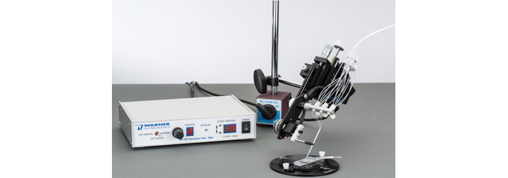
The SF-77C is a fast solution delivery device for use in patch clamp and electrophysiology studies. Control and test solutions flow continuously through adjacent delivery tubes and a stepper mechanism selects which tube is directed at the preparation. The rapid response and nominal hysteresis of the stepper allows for very short switching times. Complete solution changes are typically achieved within 20 ms for a large, 700 µm step and times are significantly shortened as the step size is decreased.
A simple but highly effective delivery device for stimulus solutions used in a variety of patch clamp and other electrophysiology applications.
Solution stimulus delivery for patch clamp and other electrophysiology studies
- Solution changes in milliseconds
- Minimal flow turbulence
- No switching through intervening solutions
- Manual or automatic step control (digital or analog)
- Modest cost and easy maintenance
- Use with most chambers or culture dishes
Multiple Solution Studies

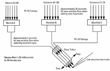
In the standard configuration, up to six different solutions can be connected to a single input manifold, which in turn is connected to one of three square glass stimulus tubes. The three tube design is superior to a two-tube design in that complex solution
An important capability of this device is that a large number of solutions can be used during the course of a single experiment irregardless of the compact size of the device. This creates the ability to use as many 15-30 different solutions in a single experiment.
This is accomplished by having up to six solutions feeding through a manifold connected to each of the three "pipes" in front of which the cell may be placed. This allows any of the pipes to have any one of the multiple solutions flowing through it at any given time. It is also possible during the course of an experiment to change the solutions flowing into any of the manifolds, allowing a virtually limitless number of solutions to be used.
Acquiring this capability is best achieved by combining the SF-77Cwith a VC-6M or VC-8M mini valve system. This package can be seen on the VC-77C webpage.
Bath vs Stepper solution flows
It's important to note that in addition to managing solution flow out of the SF-77C perfusion tubes, the flow within the larger chamber also needs to be managed since all flow velocities need to be the same.
A properly configured system will have a standard valve control system (such as the VC-8P) dedicated to controlling the main bath flow, and a separate, smaller valve control system (such as the VC-6M) dedicated to managing solution flow within the SF-77C perfusion tubes.
Having separate valve control systems for these two paths is critical for proper operation since the relative volumes and flow rates between the two are dramatically different and one controller cannot service both demands simultaneously.
Manual or External Control
The stepper mechanism can be manually controlled via the front panel or externally directed from your data acquisition program. Manually, the system can be stepped to 8 positions in 7 equally spaced steps. These same 8 positions can also be directly selected by applying an analog signal to the external analog input BNC or by passing a 3 bit word to the TTL inputs on the instrument rear panel.
The square glass tubes used for solution delivery significantly reduces mixing turbulence, allowing the SF-77C to be used for studies with both membrane patches and whole cells, even when the cells are not fixed to a substrate.
The design of the SF-77C permits the use of various size glass tubing for perfusion delivery.
The standard system is shipped with 3SG700-5 single-walled 3-barrel glass tubing which eliminates the need to glue individual barrels together. Spacing between barrels is 0.7 mm and step speed between adjacent barrels is typically 20 msec. Single barrel SG800-5 tubes (up to 5) can be used with the same holder. Micromanipulator and magnetic base not included.
SF-77CLT: Large Tube System (1.0 mm ID tubes)
Larger ports are required when using the SF-77C with larger cell structures such as the Xenopus oocyte. Solutions are delivered through 1.0 mm ID square tubes (SG1000-5) with barrel-to-barrel spacing of 1.4 mm. Micromanipulator and magnetic base not included.
SF-77C/5M: Standard System with Five Manifolds
The SF-77C/5M is the same system as the SF-77C except that it is provided with five perfusion manifolds. Micromanipulator and magnetic base not included.
SF-77CST: Fast Stepping with Theta Tubing
Very fast perfusion stepping is possible using 2-barrel Theta tubing. The technique requires close attention to detail with careful placing of the pipes and the excised patch. The tubing is pulled on a standard puller for a tip diameter of approximately 300 um and a barrel spacing of approximately 100 um.
When using 100 um steps, it is important to minimize any vibration produced by the stepper motor. This is accomplished by reducing the motor voltage via the control located on the instrument rear panel. The voltage is lowered until the vibration artifact is minimized. Any residual artifact may be removed by subtracting averaged null traces.*
Easy Set-Up
The stepper mechanism is compact, lightweight, and free of either mechanical or electrical noise. The mechanism connects to the control box with a 2 meter shielded cable and is provided with a mounting rod for attachment to a manipulator. Manifolds can support 2, 4 or 6 inputs depending on the experiment. Solutions flow from reservoirs to the manifold through PE-50 tubing and PE-10 tubing is used to connect the manifold outputs to the glass tubes. Micromanipulator and magnetic base is not included.
Specifications
Number of Steps 1 to 7 (2 to 8 positions)
Step Size Adjustable from 100 µm to 1.5 mm in 100 µm increments, with STEPS/POSITION switch
Step Speed Typically 20 ms for 700 µm step
Step Control
Manual 8 positions with POSITION selector
Analog Signal 5 positions with voltage levels 0 - 4 V, 1 V per step
Digital Signal 8 positions with 3 byte TTL signal
Max. Stepped Range 12.5 mm
Mounting Handle 6.3 mm × 10 cm (D × L)
Stepper Weight 110.5 g (including handle)
Solution Manifolds
Three manifolds supplied with each system:
MM series for SF-77C and SF-77CST
ML series with SF-77CLT
One 2-input and two 6-input manifolds are supplied
MM Series MM-2, MM-4 and MM-6 manifolds use PE-50 tubing at input and PE-10 tubing at output
ML Series ML-2, ML-4 and ML-6 manifolds use PE-50 tubing at both input and output
Solution Flow Rates Rates measured with solution reservoir height of approx. 60 cm (24 in)
With MM Series 100 µl / min
With ML Series 1 ml / min
Control Box
Size, H × W × D 5.0 × 21.2 × 19 cm
Power 100 to 130 or 220 to 250 V AC, 50/60 Hz, 10 VA
Shipping Weight 2.7 kg
Warranty 2 years, parts and labor
SF-77C/5M Standard System with 5 tubes (0.7 mm ID tubes):
Standard Fast-Step system with five (5) MM Series manifolds.
SF-77CLT: Large Tube System (1.0 mm ID tubes)
Large tube Fast-Step system with ML Series manifolds.
SF-77CST: 1 ms Stepping With Theta Tubing
Theta glass Fast-Step system with MM Series manifolds.
Easy Set-Up
The stepper mechanism is compact, lightweight, and free of either mechanical or electrical noise. The mechanism connects to the control box with a 2 m shielded cable and is provided with a mounting rod for attachment to a manipulator. Manifolds can support 2, 4, or 6 inputs depending on the experiment. Solutions flow from reservoirs to the manifold through PE-50 tubing and PE-10 tubing is used to connect the manifold outputs to the glass tubes.
