Linear Microelectrode Arrays
The LMA has been developed to assist the neuroscience community with a probe that provides multiple contacts along one or more shanks.
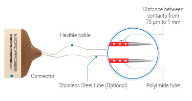
The LMAs are fabricated using Polyimide insulated Platinum/Iridium wire that is uniquely threaded through Polyimide tubing. Holes in the Polyimide tube are formed by sophisticated laser drilling at precise intervals providing electrode spacing down to 75 µm.
- A shank may contain 4-32 contact sites.
- Distance between electrode contacts ranges between 75 µm - 1 mm.
- 3D configuration with many shanks available.
- Contact size diameters are 12.5, 25, 37.5, 50 µm.
- Impedance values available between 0.1-1 MΩ.
- Contact sites are made out of Platinum/Iridium.
- Rugged design, reusable for multiple acute experiments
- Sharpened tungsten tip provide additional stiffness for easy penetration of the dural membrane.
- Shanks diameter depends on the contact site number and contact size.
- For long shanks a SS tube may be integrated above the Polyimide shank, adding stiffness and durability to the LMA.
- LMA designs are adaptable to a large number of connector types.
There are 3 different configurations of the LMA in order to satisfy the varying experimental protocols for acute as well as chronic applications. These different configurations have been identified by designating the model numbers as follows:
LMA Single-Shank
The LMA Single Shank (LMA-SS) design has been designed to offer extreme versatility for both chronic and acute applications. Because of its rugged design characteristics it can be used for many experimental trials depending on the care in handling and following the cleaning instructions after each use. The LMA uses only biocompatible and it is very well suited for chronic applications as well.

LMA - Flexible Cable
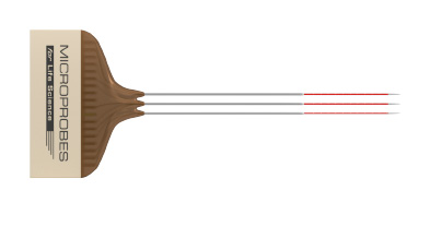
The LMA Flexible Cable (LMA-FC) is also a multi-shank design; however, the probes or probe pairs are tethered by flexible silicone encapsulated cables, which will allow the individual shanks or pairs to be semi “floating” in brain for chronic applications.

LMA - Multi-Shank
The LMA Multi-Shank (LMA-MS) design allows the researcher to specify up to 4 single shanks in the same plane or 16 shanks in a 3D array configuration. The shanks in the array can have the same design characteristics as the single shank design. The juxtaposition of each shank within the array is determined by the user specifications. It can be used for both acute and chronic applications as well.

Extra Information
Outside Diameter in microns of the Polyimide Probe
| 4 | 6 | 8 | 10 | 12 | 14 | 16 | 18 | 20 | 22 | 24 | 32 | |
| 12.5 µm | 198 | 198 | 198 | 218 | 218 | 218 | 218 | 241 | 241 | 264 | 264 | 300 |
| 25 µm | 198 | 198 | 218 | 218 | 241 | 241 | 264 | 264 | 292 | 325 | 325 | 375 |
| 37.5 µm | 218 | 218 | 241 | 241 | 264 | 264 | 292 | 325 | 325 | 370 | 370 | |
| 50 µm | 241 | 264 | 292 | 325 | 325 | 370 | 370 | 410 | 454 | 505 | 560 |
Outside Diameter of the optional Stainless Steel
| 4 | 8 | 16 | 24 | 32 | |
| 12.5 µm | 406 | 406 | 457 | 508 | 508 |
| 25 µm | 406 | 406 | 457 | 508 | 635 |
| 37.5 µm | 406 | 406 | 508 | 635 | |
| 50 µm | 406 | 457 | 635 | 851 |
Impedance value chart
| Diameter | Impedance |
| 12.5 µm Pt/Ir | 0.5 to 0.8 MΩ |
| 25.0 µm Pt/Ir | 0.3 to 0.5 MΩ |
| 37.5 µm Pt/Ir | 0.2 to 0.4 MΩ |
| 50.0 µm Pt/Ir | 0.1 to 0.3 MΩ |
Typical Impedance @ 1 kHz
Related Products:
|
Floating Microelectrode Arrays (MicroProbes) |
(MicroProbes) |
(MicroProbes) |
|
(MicroProbes) |
Pt/Ir (MicroProbes) |
Pt/Ir (MicroProbes) |
|
Optogenetic Pt/Ir (MicroProbes) |
(PDF) |


